Custom CNC Machined Aluminium Profiles
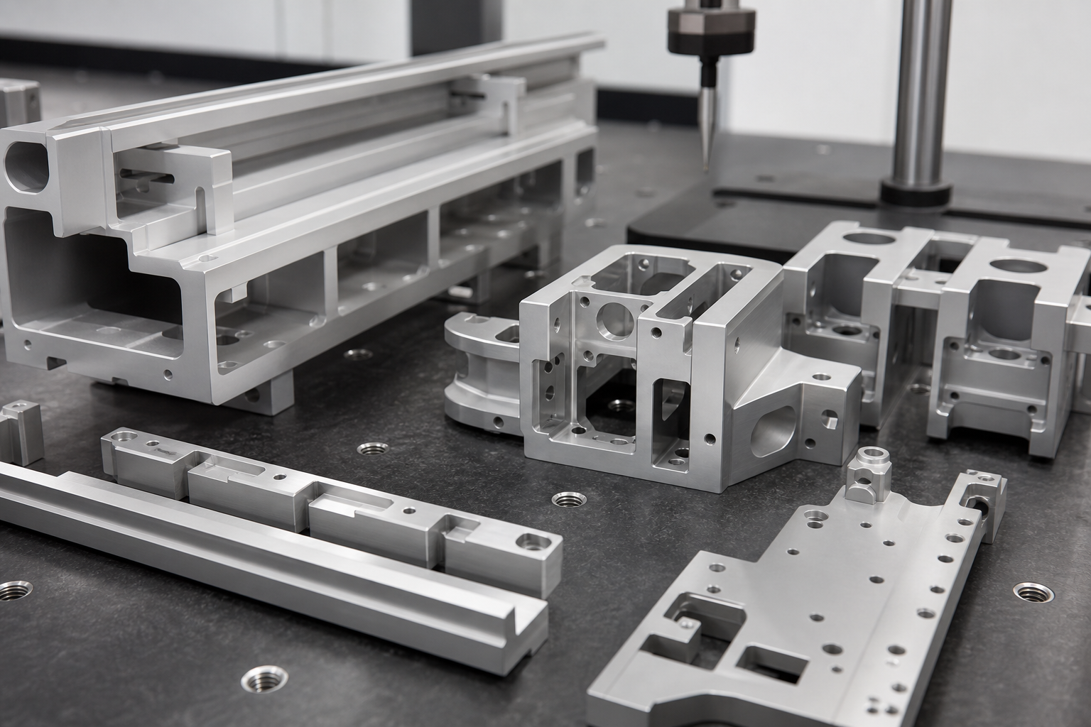
TS Aluminium fabricates precision CNC machined extrusion components. Operating multi-axis CNC routing and milling lines inside our Slacks Creek workshop, we deliver custom-cut parts to precise requirements.
Automated Routing and Tolerance Standards
Customizing aluminium profiles manually is time-consuming and prone to errors. Our facility uses automated multi-axis milling centers. The machines read digital 3D model profiles directly to rout lock cavities, hinge slots, and assembly holes, guaranteeing tolerances within ± 0.2 mm.
"By running dual mitre-saws and high-speed CNC routers side-by-side, we deliver pre-milled profile kits, streamlining on-site assembly for our building and industrial framing clients."
Machining Processing Capabilities
Our workshop handles complex fabrication operations:
- Profile Length Limits: Up to 6.5 meters single piece routing capacity.
- Drilling & Tapping: Custom countersunk holes, M4 to M16 thread taps.
- Mitre Cutting: Dual mitre saw angular cuts between 45 and 90 degrees.
- Alloy processing: Expert routing of 6063-T6, 6061-T6, and 6005-T5 grades.
Frequently Asked Questions
What dimensional tolerances can your CNC routing lines maintain?
Our automated CNC lines maintain structural tolerances of +/- 0.1mm, ensuring high assembly precision for interlocking frames.
Can you tap threads directly during CNC machining?
Yes, our CNC mills support automated tapping, countersinking, pocket milling, and precision angle cutting.
What profile lengths can be loaded onto your CNC beds?
We can machine profiles up to 6.5 meters in length in a single setup on our high-speed multi-axis CNC routing beds.
Related Projects & Case Studies
Slacks Creek Automated CNC Framing
Precision cutting and milling of 120 structural window frames with matched screw-port drill hole diameters.
Loganholme Solar Panel Mounting Rail Prep
High-speed CNC slot routing and drilling of 500 anodized aluminium mounting rails.
Request Engineering Specification
Submit your project dimensions, wind zone parameters, or target specs. Our Slacks Creek team will review and reply within 24 hours.
Engineering Analysis & Deflection Limit Calculations
TS Aluminium designs and processes all architectural and industrial systems to strict mechanical deflection limits. For clear-span structures, such as patio rafters and carport frames, the deflection is calculated under combinations of dead loads and dynamic wind pressures. The structural deflection limit is restricted to L/180 (span divided by 180) or 15mm maximum deflection under design load combinations. The elastic deflection is governed by the moment of inertia (Ix) of the profile section and the modulus of elasticity (E) of the alloy. For structural aluminium, E is taken as 70,000 MPa, as defined in AS/NZS 1664.1:1997 (Aluminium structures - Limit state design).
For example, the deflection of a simply supported rafter beam under a uniform load is calculated using the elastic formula:
deflection = (5 * w * L^4) / (384 * E * Ix)
Where 'w' represents the design load combination (including Region B wind uplift pressures), 'L' represents the clear span in millimeters, and 'Ix' represents the moment of inertia about the bending axis. For a 200mm x 50mm fluted rafter, Ix registers at 85.8 cm4, providing the stiffness needed to support spans up to 5.0 meters under N4 wind classifications.
For T-slot profiles used in machinery frames, stiffness is calculated to ensure linear rail alignment under static loads. Our modular frames feature structural alloys like 6005-T5, which offer high mechanical limits. By matching the moment of inertia tables with the dynamic load cycle limits of your equipment, our engineers select the correct T-slot profiles (TS 3030, TS 4040, or TS 8080) to prevent structural vibrations and extend tool lifespans.