Custom Extrusions & OEM Design Services
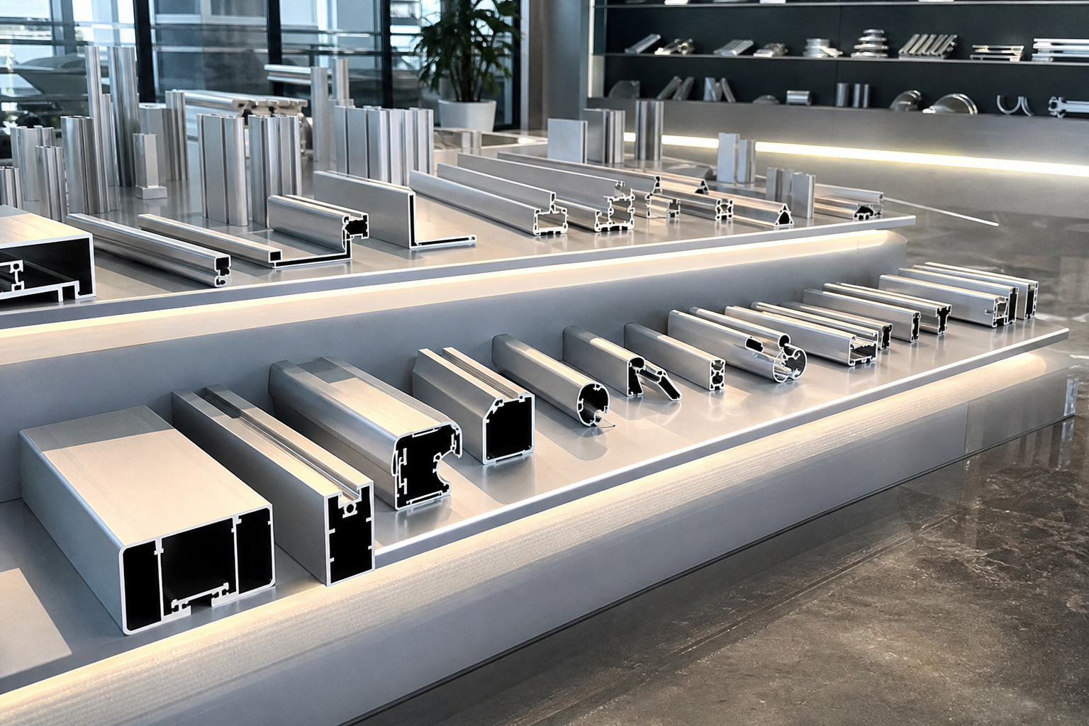
TS Aluminium provides custom aluminium extrusion design and tooling die setup. Sourced from high-grade structural alloys, we design and extrude custom profiles matching specific architectural or industrial geometry parameters.
Custom Die Tooling and Press Workflow
When standard profiles don't meet design requirements, a custom die is engineered. The process begins with CAD drawings of the cross-section. Our designers run stress calculations and fluid flow simulations to optimize material distribution. The tool steel die is then processed to shape.
"By managing custom die setup and sample production log cycles, we ensure that new profiles are tested and verified for dimensions and hardness parameters before full production."
Custom Extrusions Guidelines
We process custom designs according to engineering limits:
- Minimum Wall Thickness: 1.2mm for architectural profiles; 2.5mm for heavy load beams.
- Profile Weight Limits: 0.15 kg/m up to 12.5 kg/m configurations.
- Alloys Sourced: 6063 (architectural), 6060 (brackets), 6061-T6 (heavy structural).
- Die Lead Times: 3–4 weeks for sample approval; 2 weeks for full batch production.
Frequently Asked Questions
What is the typical lead time for custom extrusion tooling?
Custom mould and tool die development takes 3-4 weeks from CAD approval, followed by sample extrusion testing and inspection and verification.
What extrusion alloy options are available?
We offer architectural alloy 6063, structural alloy 6061, and high-strength alloy 6005-T5, heat-treated to T5 or T6 tempers.
What is the minimum order quantity (MOQ) for custom runs?
Our standard MOQ for custom extrusion runs is 500kg per profile cross-section, supporting prototype runs and commercial projects.
Related Projects & Case Studies
Wacol OEM Automotive Bracket Profiles
Custom die development and extrusion of specialized mounting brackets in structural 6061-T6 alloy.
Murarrie Architectural Cladding Panel Frames
Extrusion of custom interlocking structural frame sections for a commercial office facade project.
Request Engineering Specification
Submit your project dimensions, wind zone parameters, or target specs. Our Slacks Creek team will review and reply within 24 hours.
Engineering Analysis & Deflection Limit Calculations
TS Aluminium designs and processes all architectural and industrial systems to strict mechanical deflection limits. For clear-span structures, such as patio rafters and carport frames, the deflection is calculated under combinations of dead loads and dynamic wind pressures. The structural deflection limit is restricted to L/180 (span divided by 180) or 15mm maximum deflection under design load combinations. The elastic deflection is governed by the moment of inertia (Ix) of the profile section and the modulus of elasticity (E) of the alloy. For structural aluminium, E is taken as 70,000 MPa, as defined in AS/NZS 1664.1:1997 (Aluminium structures - Limit state design).
For example, the deflection of a simply supported rafter beam under a uniform load is calculated using the elastic formula:
deflection = (5 * w * L^4) / (384 * E * Ix)
Where 'w' represents the design load combination (including Region B wind uplift pressures), 'L' represents the clear span in millimeters, and 'Ix' represents the moment of inertia about the bending axis. For a 200mm x 50mm fluted rafter, Ix registers at 85.8 cm4, providing the stiffness needed to support spans up to 5.0 meters under N4 wind classifications.
For T-slot profiles used in machinery frames, stiffness is calculated to ensure linear rail alignment under static loads. Our modular frames feature structural alloys like 6005-T5, which offer high mechanical limits. By matching the moment of inertia tables with the dynamic load cycle limits of your equipment, our engineers select the correct T-slot profiles (TS 3030, TS 4040, or TS 8080) to prevent structural vibrations and extend tool lifespans.